
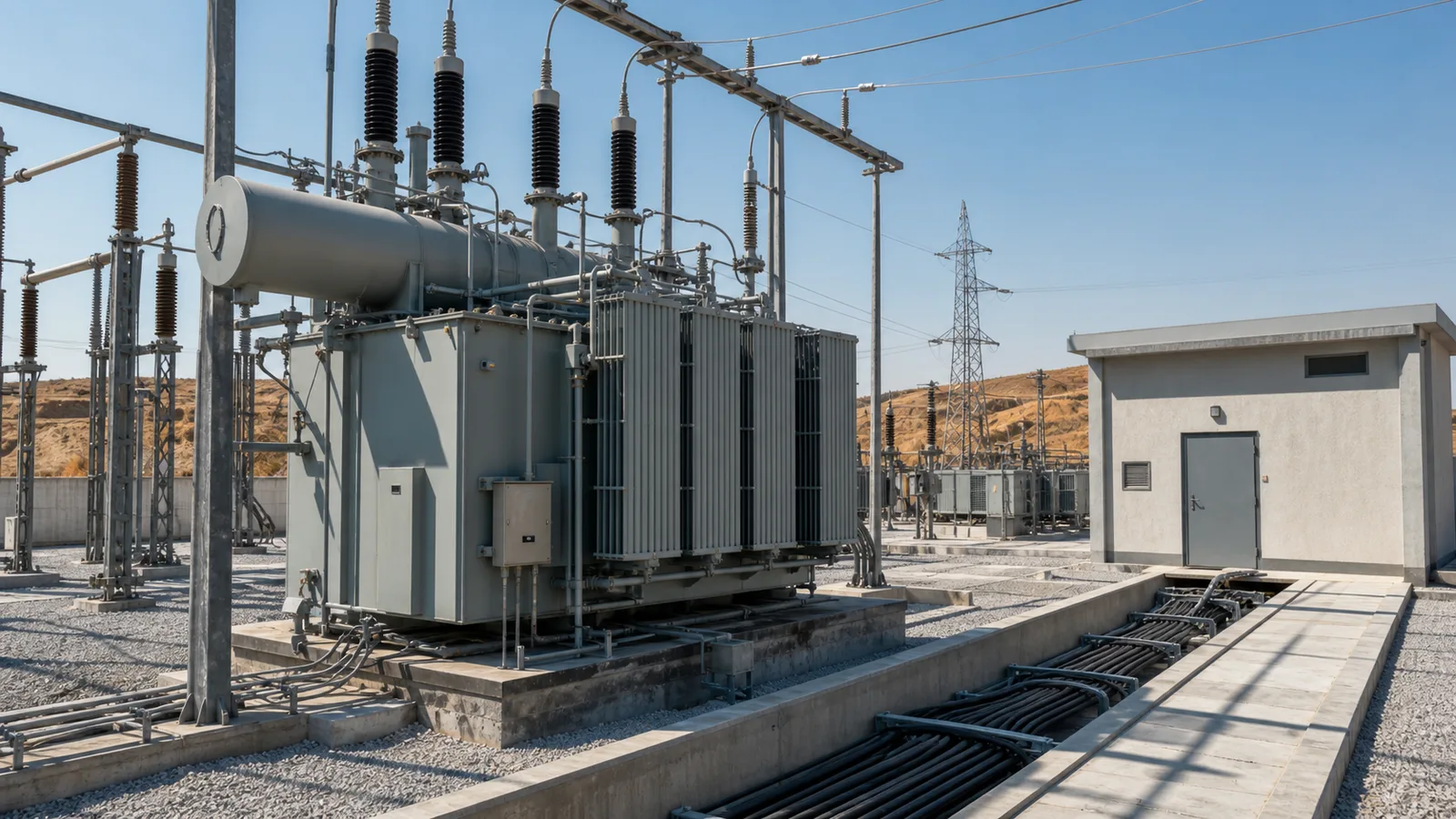
Turkey transformer application
Turkey Transformer Temperature Controller Retrofit
Turkey transformer temperature controller retrofit configuration covering BWY oil indication, BWR winding control, signals and replacement checks.
Transformer and Operating Environment
Oil-immersed transformer retrofits in Turkey often begin with an existing oil temperature indicator and winding temperature indicator that require replacement while the original control scheme remains in service.
A retrofit begins with the installed instruments rather than a preferred catalog model. Front and rear photographs, complete nameplates, dial ranges, terminal references, capillary routes, bulb dimensions and mounting drawings establish the functional and mechanical baseline.
Temperature Monitoring Needs
The replacement must preserve the meaning of each temperature value. The oil temperature controller follows top oil at the thermometer pocket. The winding temperature controller represents the transformer-specific simulated winding value through its current-related heating arrangement.
Cooling, alarm and trip contacts require a terminal-by-terminal comparison. Remote Pt100 or 4-20 mA signals must retain their scale and receiving-input compatibility. A similar enclosure or partial BWY or BWR family name is not enough to prove interchangeability.
Suitable OTI and WTI Arrangement
A suitable selection path pairs a BWY oil temperature controller with a BWR winding temperature controller after the full suffixes and drawings have been compared. The scale, switch count, contact duty, capillary length, bulb, thread and environmental construction remain subject to model confirmation.
For the WTI path, the current-transformer secondary data and compound transmitter or converter arrangement must be captured from the original system. The simulated rise belongs to the transformer thermal design and should not be transferred from an unrelated unit.
Cooling, Alarm and Remote Signals
Assign every contact to a documented function such as cooling stage, high-temperature alarm or trip input. Confirm whether an interposing relay separates the instrument contact from the controlled load.
For remote monitoring, document the signal type, loop supply, polarity, temperature scale and panel input. Commissioning compares local indication with the remote value and verifies every downstream action.
Installation and Commissioning Checklist
Related Transformer Temperature Products
Confirm the complete suffix, technical documents and project interfaces before selecting a final model.
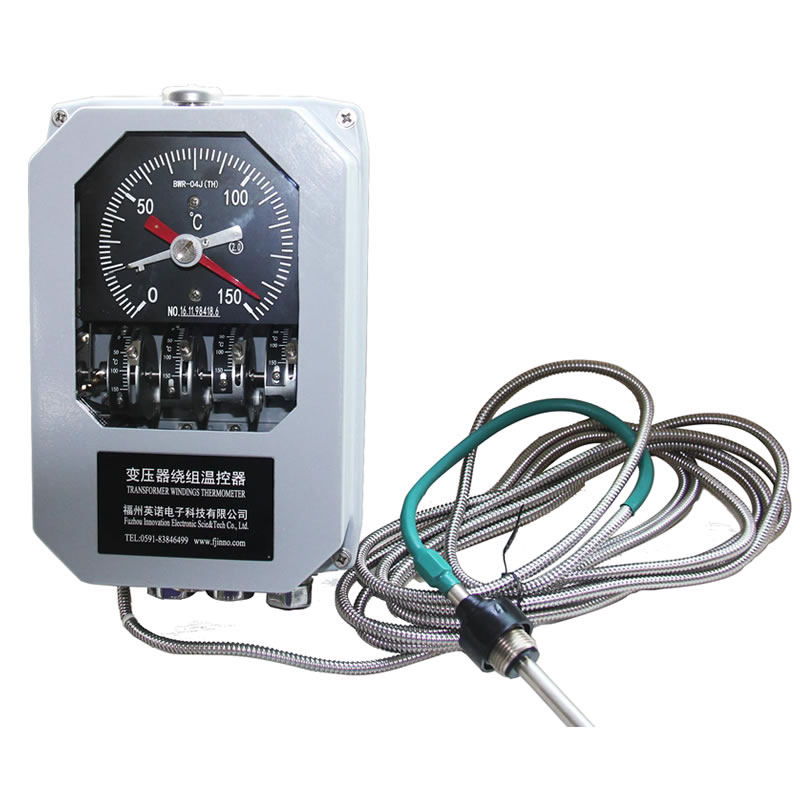
BWR-04/06 Winding Temperature Controller
A BWR winding thermometer family for simulated winding temperature, switch control and remote 4-20 mA configurations.
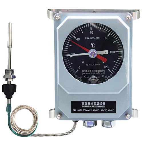
BWY-802/803 Oil Temperature Controller
A transformer top-oil temperature controller with local indication, Pt100 remote signal and adjustable control contacts.
Application guidance: Transformer Temperature Controller Retrofit