How Does Transformer Temperature Controller Retrofit Work?
Capture the installed configuration
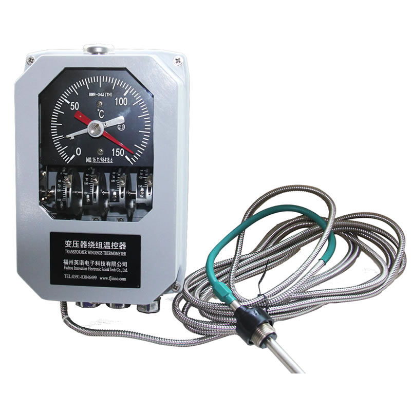
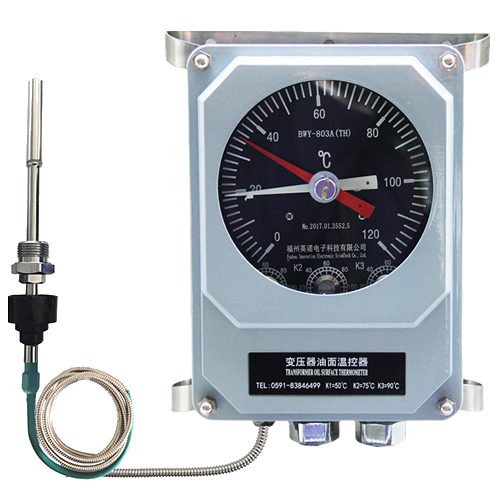
Photograph the front, nameplate, terminals, mounting points, sensing bulb connection and capillary route. Record the complete model code and scale. Obtain the wiring diagram and note the function of each connected contact.
Measure the mounting footprint and confirm the thermometer pocket, bulb diameter, insertion depth and thread. A product that looks similar on a catalog page may not fit the existing arrangement.
Separate mandatory matches from improvements
A direct replacement normally preserves scale, contact quantity, contact duty, output, supply and mechanical interface. A modernization may intentionally change the remote signal or add a digital display, but that change requires panel and drawing review.
Identify which features are mandatory for immediate interchangeability and which can change. This prevents an attractive upgrade from creating an unplanned wiring or commissioning project.
Check the WTI current circuit
A WTI replacement also requires the current-transformer input and compound-transmitter characteristics. The load-current simulation must correspond to the transformer design. Do not transfer set points or converter settings without verification.
Trace the CT circuit and observe applicable safety procedures. Current-transformer secondary circuits require controlled handling and must not be casually opened while energized.
Plan a documented changeover
Before removal, tag every conductor and record the original settings. Install the new device, protect the capillary and confirm the mechanical seal.
Function-test local indication, remote output, cooling stages, alarm and trip interfaces. Update the equipment record with the new model, scale, terminal map and set points.