How Does Power Transformer Temperature Monitoring Work?
Define the thermal variables before choosing hardware
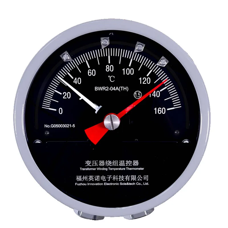
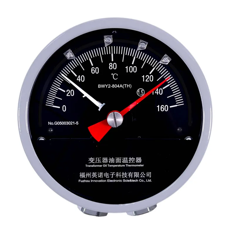
A power transformer can expose several temperature values. A top-oil indicator follows the oil near its sensing pocket. A winding temperature indicator adds a load-related simulated rise. Direct winding hot-spot measurement requires a different sensing arrangement. The specification should name the required value instead of using the general phrase transformer temperature.
The operating purpose is equally important. Local indication, cooling-stage control, high-temperature alarm, trip input and remote trending have different reliability and interface requirements. Assign each function to an instrument contact, transmitter or supervisory controller before model selection.
Coordinate OTI and WTI functions
An OTI commonly provides the reference top-oil value and contacts for fan or pump stages. A WTI follows simulated winding temperature and can provide additional cooling, alarm or trip contacts. Their set points should follow the transformer manufacturer thermal study and project protection coordination.
When both instruments send remote values, confirm scaling, isolation, cable type and receiving-input configuration. The control room should label values as top oil or winding indication so operators do not compare different thermal quantities as though they were identical.
Specify installation interfaces
The drawing should define instrument mounting, thermometer pockets, bulb size, thread, capillary length, bend limits, routing protection and terminal access. The selected capillary must reach the instrument without tension or a tight coil.
For a retrofit, obtain the old nameplate, dial scale, mounting footprint, pocket dimensions and wiring diagram. A model family match does not guarantee mechanical or electrical interchangeability.
Commission the complete control chain
Commissioning should test local indication, each adjustable contact, cooling relay operation, alarm annunciation, trip interface and the remote analog or digital value. Record actual set points and terminal numbers in the final drawings.
A loop check from field instrument to control-room display catches polarity, scaling and terminal errors before the transformer is placed under load. Periodic inspection should include the capillary, enclosure sealing, dial readability and contact operation.